

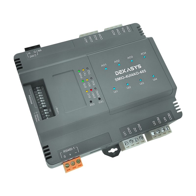

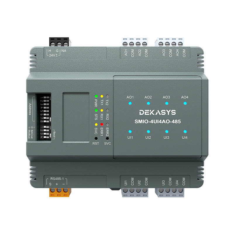
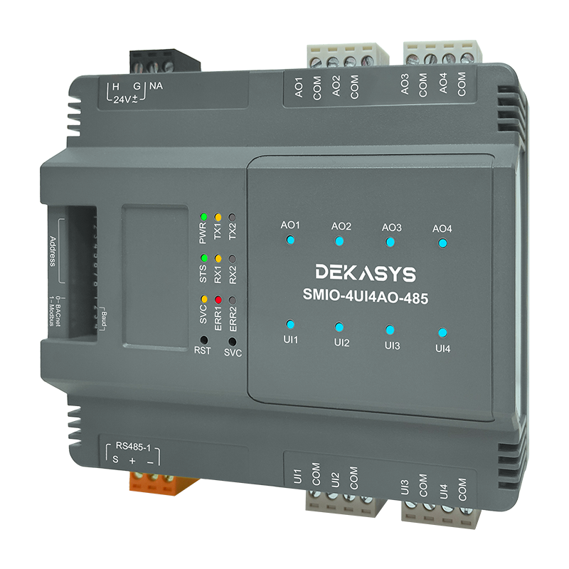


DEKASYS 8-point Remote IO module SMIO-4UI4AO-485

Multi-Protocol Support
Seamlessly integrates with BACnet MS/TP, BACnet IP, Modbus RTU, and Modbus TCP protocols, ensuring compatibility across diverse automation ecosystems.

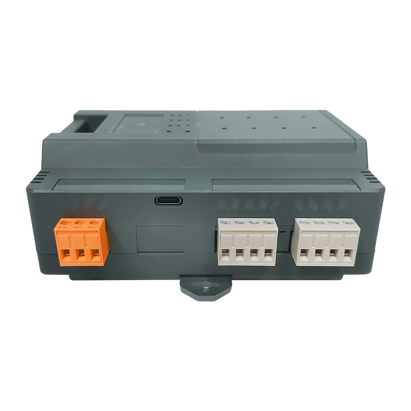
Remote Firmware Management
Enables in-system firmware upgrades and parameter adjustments via USB connectivity, eliminating downtime for hardware replacements.

Manual Override Analog Output
Features a slide switch to toggle between 0–10V, 0–20mA, or 4–20mA output modes, complemented by a trimmer potentiometer for precise signal calibration.

Intuitive Hardware Configuration
Address and baud rate settings are simplified via a DIP switch panel, streamlining deployment in time-critical installations.
|
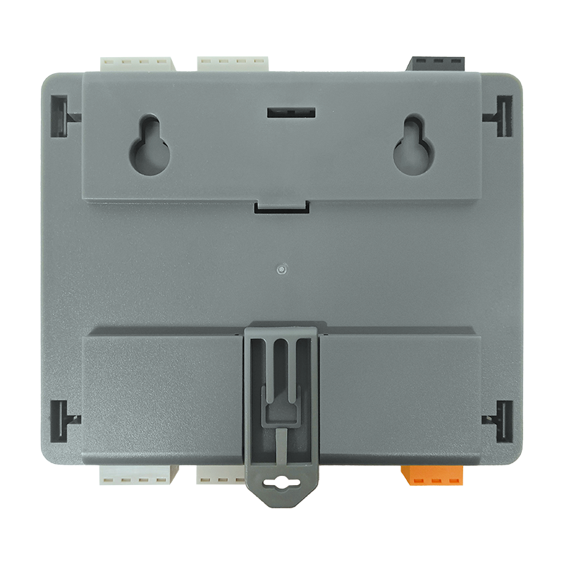
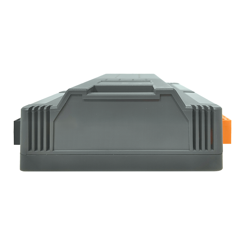
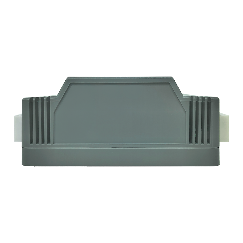
Dimension |
131.4x107.1x51.7mm(±0.5mm) |
|
Casing Material |
UL 94 ABS + PC |
|
Weight |
TBA |
|
Power Supply |
24V AC +20%/-15% or 24V DC ±5% |
|
Consumption |
<10W |
|
Current Rating |
1A at 24VAC/VDC |
|
Operating Temp |
32 to 131°F (0 to 55 °C) |
|
Storage Temp. |
-4 to 185 °F (-20 to 85 °C) |
|
Operating Humidity |
0% to 95% relative humidity non-condensing |
|
IP Waterproof |
IP20 |
|
12-bits with PGA |
|
|
Voltage |
0 - 10V (±0.01V), 0 - 5V (± 0.01V) |
|
Current |
4 - 20mA (±0.01mA), 0 - 20mA (±0.01mA) |
|
Resistance |
0 - 30K , 0 - 10K, 0 - 1.5K |
|
Thermister |
NTC : 10K TYPE 2/3, 3K, 20K (±0.1 ℃) |
|
Sensor |
RTD : 1K Balco, 1K Platinum (±0.2 ℃) |
|
12-bits DAC |
|
|
Current |
0 - 20mA, 4 - 20mA (Max load resistance, 800Ω) |
|
Voltage |
0 - 10V |
|
Certifications |
CE, FCC, BTL |
-

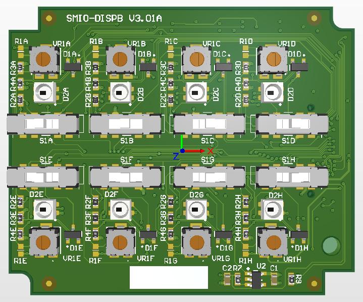
Analog Output Channel
Analog output can be either voltage output or current output.
The RGB LED colour will change from a cool colour of Blue, through Green and then bright Yellow showing that the analog output amplitude in the increasing order. -

Analog Input Channel
Analog input can be either voltage input, current input or resistive input.
The RGB LED colour will change from a cool colour of Blue, through Green and then bright Yellow showing that the analog input amplitude in the increasing order. When the analog input channel is configured as resistive input, and when the terminal is not terminated with any resistive load, or the wire is broken, the analog input channel detects a very high resistance, and will light up the RGB LED with pure RED colour signifying the analog channel is in error mode. -

Analog Input Channel And Analog Output
Below table summarize the RGB LED colour display in specific configuration and type of IO channel:
Type Of IO
Configuration
Colour
Analog Output
0 to 10V or 0 to 20mA
Blue, through Green and then bright Yellow
4 to 20mA
< 4 mA in error state, Red.
Blue, through Green and then bright Yellow
Analog Input
0 to 10V or 0 to 20mA
Blue, through Green and then bright Yellow
4 to 20mA
< 4 mA in error state, Red.
Blue, through Green and then bright Yellow
0 Ohm to 20k Ohm
Blue, through Green and then bright Yellow
DEKASYSAnalog Output Manual Override
With Analog Output Manual Override, user can manually override the current output state using the slide switch and the trimmer.
|
Slide Switch Position |
Mode |
Description |
|
Left |
Voltage Mode |
Analog output is in Voltage mode, turning the trimmer adjust the output voltage. |
|
Middle |
Current Mode |
Analog output is in Current mode, turning the trimmer adjust the output current. |
|
Right |
Auto/A |
Analog Output is controlled by network command. |
The trimmer is increasing when turning clock wise and decreasing when turning anti-clock wise.