
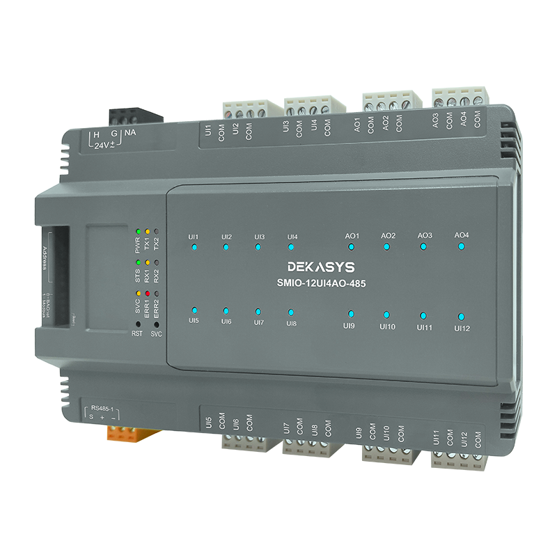
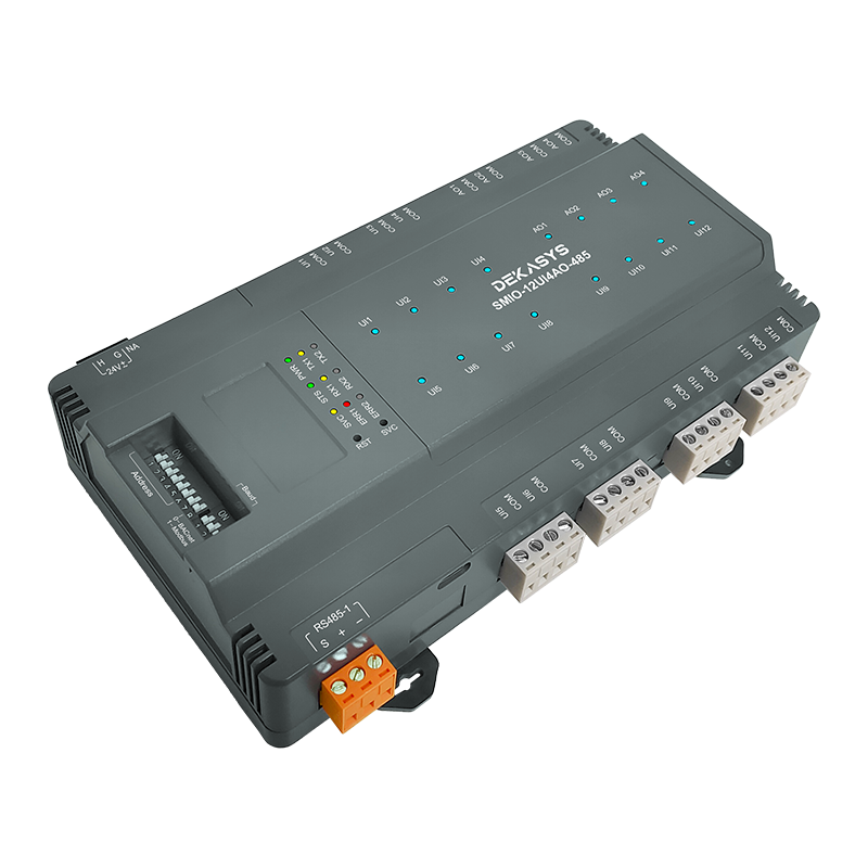


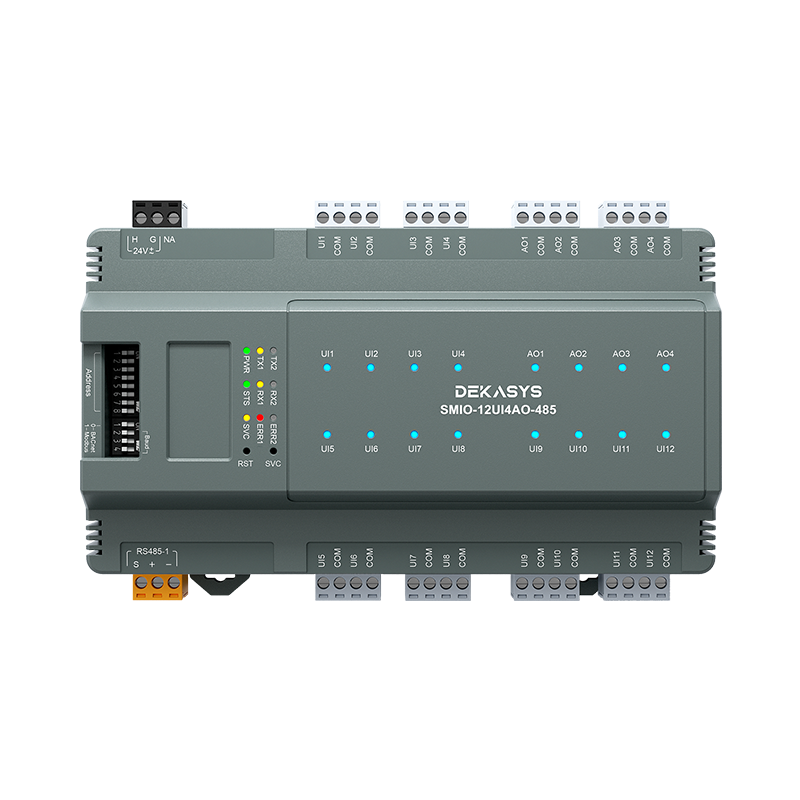


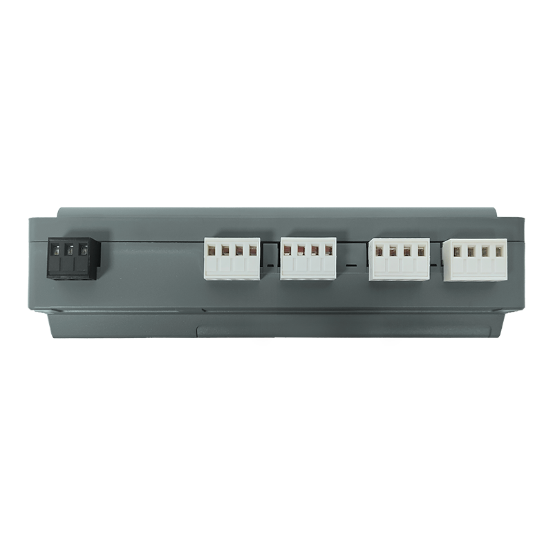


DEKASYS 16-point Remote IO module SMIO-12UI4AO-485

Protocol Support
Supports the standard open communication protocols BACnet MS/TP, BACnet IP, Modbus RTU, and Modbus TCP.

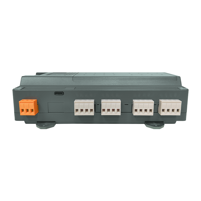
Online Firmware Updates
The controller’s firmware can be upgraded and configured via USB COMM Port.

Analog Output Settings
The analog output type can be chosen using a slide switch, and the amplitude can be fine-tuned with a trimmer to ranges of 0 V–10 V, 0 mA–20 mA, or 4 mA–20 mA.

DIP Switch Configuration
The DIP switch provides a fast and convenient way to set the address.
|
Dimension |
193.2x107x51.2mm(±0.5mm) |
|
Casing Material |
UL 94 ABS + PC |
|
Weight |
TBA |
|
Power Supply |
24V AC +20%/-15% or 24V DC ±5% |
|
Consumption |
<10W |
|
Current Rating |
1A at 24VAC/VDC |
|
Operating Temp |
32 to 131°F (0 to 55 °C) |
|
Storage Temp. |
-4 to 185 °F (-20 to 85 °C) |
|
Operating Humidity |
0% to 95% relative humidity non-condensing |
|
IP Waterproof |
IP20 |
|
12-bits with PGA |
|
|
Voltage |
0 - 10V (±0.01V), 0 - 5V (± 0.01V) |
|
Current |
4 - 20mA (±0.01mA), 0 - 20mA (±0.01mA) |
|
Resistance |
0 - 30K , 0 - 10K, 0 - 1.5K |
|
Thermister |
NTC : 10K TYPE 2/3, 3K, 20K (±0.1 ℃) |
|
Sensor |
RTD : 1K Balco, 1K Platinum (±0.2 ℃) |
|
12-bits DAC |
|
|
Current |
0 - 20mA, 4 - 20mA (Max load resistance, 800Ω) |
|
Voltage |
0 - 10V |
|
Certifications |
CE, FCC, BTL |
-

Analog Output Channel
Analog output may take the form of voltage or current output.
The RGB LED's color transitions from a cool blue to green and then to a bright yellow, illustrating the increasing order of the analog output amplitude. -

Analog Input Channel
Analog input can take the form of voltage input, current input, or resistive input.
The RGB LED's color transitions from a cool blue to green and then to a bright yellow as the analog input amplitude increases. If the analog input channel is set to resistive input mode and there is no resistive load connected or the wire is broken, the channel detects an extremely high resistance. In this case, the RGB LED will turn on with a pure red color, indicating that the analog channel is in an error state. -

Analog Input Channel And Analog Output
Below table summarize the RGB LED colour display in specific configuration and type of IO channel:
Type Of IO
Configuration
Colour
Analog Output
0 to 10V or 0 to 20mA
Blue, through Green and then bright Yellow
4 to 20mA
< 4 mA in error state, Red.
Blue, through Green and then bright Yellow
Analog Input
0 to 10V or 0 to 20mA
Blue, through Green and then bright Yellow
4 to 20mA
< 4 mA in error state, Red.
Blue, through Green and then bright Yellow
0 Ohm to 20k Ohm
Blue, through Green and then bright Yellow
DEKASYSAnalog Output Manual Override
With Analog Output Manual Override, user can manually override the current output state using the slide switch and the trimmer.
|
Slide Switch Position |
Mode |
Description |
|
Left |
Voltage Mode |
Analog output is in Voltage mode, turning the trimmer adjust the output voltage. |
|
Middle |
Current Mode |
Analog output is in Current mode, turning the trimmer adjust the output current. |
|
Right |
Auto/A |
Analog Output is controlled by network command. |
The trimmer is increasing when turning clock wise and decreasing when turning anti-clock wise.